Skip to content
Back to Overview

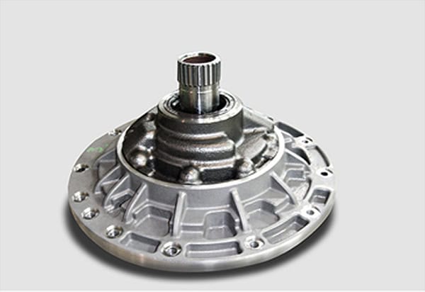
Transmission Oil Pumps

Custom-engineered oil pump systems for automatic, double clutch, and continuously variable transmissions. Designed for stable hydraulic supply, low pulsation, and reliable lubrication under demanding drivetrain conditions.

Transmission Oil Pumps

Stable Hydraulic Supply

Reliable pressure for shifting and lubrication

Low Noise / NVH

Optimized for sensitive drivetrain acoustics

Low Pressure Pulsation

Stable delivery across operating speeds

Transmission-Specific Design

Adapted to AT, DCT, and CVT demands

Typical applications for transmission oil pumps

Where TPV engineering supports stable oil pressure, lubrication, cooling, and hydraulic control in modern transmission systems.

Automatic Transmissions

Reliable hydraulic supply for torque-converter transmissions, shifting circuits, lubrication paths, and cooling flow requirements.

Double Clutch Transmissions

Fast pressure build-up and stable delivery for clutch actuation, cooling, lubrication, and rapid transient operating conditions.

Continuously Variable Transmissions

High-pressure oil pump concepts for CVT systems requiring stable hydraulic performance across wide ratio and load ranges.

Transmission System Integration

We adapt pump architecture, gear set, housing, and hydraulic interfaces to your transmission layout, oil circuit, and operating strategy.

Hydraulic Circuit Integration

Pump concepts developed around pressure supply, lubrication paths, cooling flow, shifting circuits, and available hydraulic interfaces.

Transmission Housing Integration

Integrated into compact transmission packages with attention to suction conditions, drive interface, mounting position, and oil routing.

Why choose Transmission Oil Pumps?

Transmission oil pumps must deliver stable pressure and flow for lubrication, cooling, and hydraulic actuation while meeting strict NVH and packaging requirements.

Hydraulic Stability

Reliable pressure supply for shifting, actuation, lubrication, and cooling circuits across dynamic operating conditions.

NVH-Focused Design

Gear geometry and system design optimized to reduce noise, vibration, and pressure pulsation in sensitive drivetrains.

Application-Specific Concepts

Pump systems adapted to the hydraulic and packaging requirements of AT, DCT, and CVT architectures.

Core Technology

Duocentric-IC Gearing

Trochocentric-developed gearing for compact transmission oil pump systems. Designed to support low pulsation, high volumetric efficiency, and stable hydraulic delivery in demanding drivetrain applications.

Trochocentric Developed

Optimized clearances & Roll-off

Standard Gerotor

Higher Pulsation & Wear

  • Low pressure pulsation for sensitive transmission hydraulics
  • Reduced leakage gaps for improved volumetric efficiency
  • Smoother tooth engagement for lower NVH emission
  • Suitable for AT, DCT, and CVT oil pump architectures
Deep Dive: Trochocentric Tech
Duocentric-IC Technology

Key Performance Targets for Transmission Oil Pumps

Low Noise / NVH Targets

Reduce airborne noise, structure-borne vibration, and gear-related acoustic excitation in sensitive drivetrain environments.

Low Pulsation at Operating Speed

Minimize pressure pulsation and improve hydraulic stability across shifting, lubrication, and cooling operating ranges.

More Flow in the Same Package

Increase hydraulic performance without expanding the available transmission housing envelope or changing the core layout.

Stable Relief Valve Behavior

Eliminate oscillation and improve pressure regulation during dynamic shifting, temperature changes, and load transitions.

How it works

From requirements to validated prototypes

A clear workflow tailored to your application, covering concept development, simulation, prototyping, validation testing, and series ramp-up with production partners.
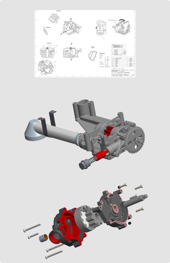
development process
1

Requirements

Kick-off & application review

Output:

Requirement specification + application targets

2

Concept

System layout & gear set design

Output:

3D design + initial drawings

3

Simulation

Hydraulic calculations & CFD

Output:

Hydraulic performance data + simulation results

4

Prototyping

Prototype manufacturing

Output:

Functional prototypes for test bench validation

5

Validation

Prototype test rig optimization

Output:

Validated pump system ready for production preparation

Series

Ramp-up with production partners

Output:

Series-ready production setup with established partners

Validated Quality

Every prototype is optimized on our prototype test rig for hydraulic stability, low pressure pulsation, low noise behavior, and reliable flow delivery. Transmission oil pump prototypes are typically available within 3–4 months after design freeze and are 100% tested with full test reports.

Prototype test rig optimization
100% tested with test reports
Typical prototype lead time: 3–4 months after design freeze

FAQs

Quick answers to practical engineering questions about transmission oil pump development, hydraulic stability, NVH, pressure pulsation, and integration into AT, DCT, and CVT systems.

Typical drivers include pressure instability, excessive pulsation, NVH issues, packaging limits, higher cooling demand, efficiency targets, or the need to adapt an existing pump concept to a new AT, DCT, or CVT architecture.

Yes. The development process is consistent, but the hydraulic targets differ. AT systems often focus on reliable pressure and lubrication, DCT systems on rapid pressure build-up and clutch cooling, and CVT systems on stable high-pressure supply.

Ideally before the pump envelope and hydraulic interfaces are fully frozen. Early involvement makes it easier to optimize suction conditions, gear set design, pressure behavior, packaging, and NVH before costly layout constraints are fixed.

Useful inputs include pressure and flow targets, speed range, oil temperature range, transmission type, circuit layout, suction conditions, packaging envelope, drive interface, NVH limits, and known pulsation or pressure-control issues.

Often, yes. TPV can evaluate the available space, gear geometry, leakage gaps, suction path, and pressure behavior to identify improvement potential within the existing housing or interface constraints.

Prototype systems can be tested for flow delivery, pressure stability, pulsation, NVH behavior, leakage, power consumption, and relief valve behavior before the concept is prepared for series production with partner manufacturers.

Back To Top