
From pump concept to predictable hydraulic behavior
In this phase, the pump concept is evaluated through hydraulic calculation, simulation, and CFD-supported analysis. The goal is to understand flow delivery, pressure behavior, suction conditions, leakage paths, and pulsation risks before physical testing begins.
What we need for simulation, CFD & hydraulics
Reliable simulation results depend on realistic input data. Geometry, operating conditions, oil properties, and hydraulic targets define how the oil pump system is evaluated.


What simulation & CFD evaluates


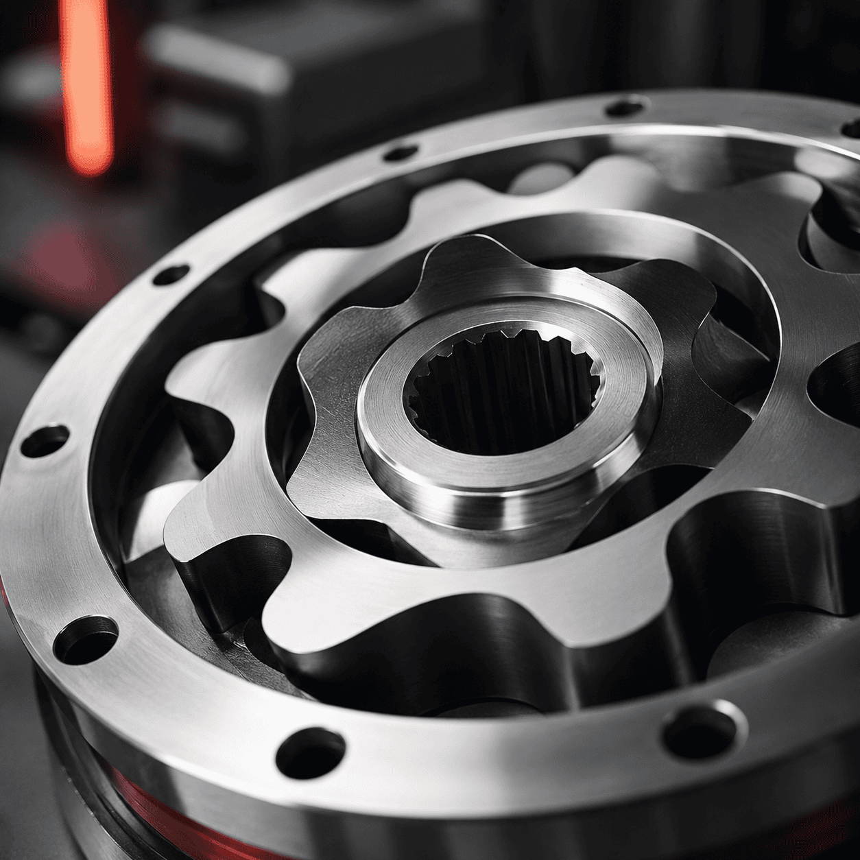
A compact workflow for hydraulic evaluation
We review geometry, operating points, oil data, pressure targets, flow demand, and available system constraints.
We prepare the hydraulic model, define boundary conditions, and focus the simulation scope on the relevant pump behavior.
We evaluate flow delivery, pressure behavior, suction conditions, pulsation, leakage effects, and hydraulic losses.
The results are translated into practical recommendations for geometry, interfaces, flow paths, and prototype preparation.
The output of hydraulic simulation


Clear hydraulic insight before prototype testing.
Simulation, CFD, and hydraulic analysis help reduce uncertainty before physical prototypes are built. They support better design decisions, targeted prototype preparation, and more focused validation testing on the test rig.
FAQs
Quick answers to practical questions about oil pump simulation, CFD, hydraulic analysis, flow behavior, pressure stability, and prototype preparation.
Typical simulation work evaluates flow delivery, pressure behavior, suction conditions, leakage effects, hydraulic losses, pulsation tendency, and critical flow paths within the pump system.
CFD helps identify restrictions, unstable flow areas, suction problems, cavitation risks, and pressure losses before hardware is produced. This can reduce redesign effort and make prototype testing more focused.
Useful inputs include pump geometry, CAD data, pressure and flow targets, RPM range, oil temperature, viscosity, suction and outlet conditions, leakage assumptions, and relevant operating points.
No. Simulation supports better decisions before testing, but physical validation is still needed. Test rig results confirm real flow delivery, pressure stability, leakage, pulsation, NVH behavior, and power consumption.
Simulation can help identify pressure ripple sources, flow discontinuities, outlet effects, and interaction points in the hydraulic circuit. These insights support targeted changes before prototype validation.
The results usually feed into CAD refinement, prototype planning, manufacturing preparation, and validation testing. Simulation findings help define what should be measured and optimized on the test rig.